by Curlydock
The simplest radio
receivers require no batteries, gasoline, coal, oil, nuclear, wind, geothermal, tidal, or solar power.
And, they are indeed simple. Using them and building them out of parts found in the junkbox or scavanged from yard-sales will not hurt the planet and will not make Greedy Gates even richer.
I built this one for a recent experiment. It has only five electrical components. The only power it requires exists in the signal it receives. In our metro area (Louisville, Ky) in one afternoon I received eleven stations loud and clear. These transmitters were all local and within about a twelve mile radius. Their powers ranged between 500 watts and 50 Kilo-watts. The 500 watt station is roughly 5 miles away.
These radios are variously called crystal sets, crystal radios, or foxhole radios. In the “foxhole” variety, the home-made simplicity includes the signal detector, which is a razor blade and piece of pencil lead!
The All-Powerful Antenna
For this type of radio to work well, every consideration must be made to conserve the precious power that arrives in the signal. This typically requires a very long and high outdoor antenna and a good ground connection. This antenna is a wire between 30 and several hundred feet long. The ground connection can be a cold water pipe (but only if it is metal into the earth) or a metal rod or pipe driven 4 to eight feet or so into the earth. Good performance depends on a good ground connection and such connections are sometimes hard to come by. For safety, one should also install some kind of lightning arrestor and disconnect the radio during bad weather. Also, one should install the antenna well clear of power lines. All this may be difficult to impossible in a metro environment.
Until this experiment,
I believed crystal radios could not be made portable or operate effectively with an indoor antenna. Now I know otherwise. You still can’t stick it in a pocket, but you can easily carry the radio and antenna around while you listen to a station.
Given the appearance of the antenna, you would attract a lot of attention outside. Whether attracting attention is good or bad depends on you and your needs and the particular setting, I guess.
Anyway, here is a picture of the crystal set and antenna I built and used in this experiment:

It sits in the comfortable chair, for scale, next to the special loop antenna. The loop antenna has a 32-inch outside diameter. This installment is really about the antenna, because that is what made the radio able to receive as well as it does.
The antenna is not as heavy as it looks because the bulky part is cut from thick sheets of styrofoam insulation, which is mostly gas and therefore light. The rings are glued like a sandwich over the sector fingers, which were made of scrap pieces of a wall covering that resembles pressed fiber board (like some clip boards are made of). The antenna can easily be lifted from the pvc pipe support and carried around slung across your shoulder, all the while supplying signal to the radio.
Other materials can be used. In other versions, I used bamboo chopsticks taped in pairs on either side of wood popsicle sticks, creating the slot that the cable is woven through. I have also cut the whole ring and set of sectors and slots from large sheets of cardboard. To strengthen large diameters, you might want to use white glue or flour paste to build up several layers of cardboard. Use styrofoam, plastic, wood, cardboard, pvc pipe or plexiglass but keep the use of metal in the antenna to a bare minimum. Even the non-metal structure should be kept to the minimum needed for support of the wire. For example, if you use large sheets of cardboard, cut out the middle so that it is a ring instead of a disc. Discarding anything that is not needed in the viscintiy of the antenna will improve it’s quality. Ideally, if you can figure out a way to support the wire on nothing but air, more power to you (and to your radio)!
The weave of the cable is important. Here is a close up showing how this weave was accomplished on this antenna:
This neat alternation is possible only with an odd number of sectors. Use 5, 9, or 11 sectors, but not 6, 10 or 12, etc. No, it is not numerology. I am not superstitious. Try it and see!
The reason for this weave is that it keeps the individual turns of wire separated from each other. The separation is needed because if the wires lay close together, as in a close-wound coil, something called capacitance will build up with each added turn to such a degree that it spoils the quality of the coil. I know it sounds like I am just pulling this out of my…, but, believe me, it’s true!
The wire
I used in the antenna was about 90 or 100 feet of cable from a spool labeled: “100-Ft. (30.4m) Telephone-Station Wire 8-con.(4 twisted pair) 24-Ga. Solid Color-coded.”
It was copper wire.
I first wound the whole antenna and then went back and cut each turn.
That can be done neatly if you cut all the cable on each side of one particular support slot but on only one side of the plane of the disk. That sounds complicated, but however you end up with a coil of eleven turns with one tap per turn and an extra tap for the odd end is ok with me.
The eight individual wires in these cuts were then cleaned of insulation and soldered together. The ends were then re-joined as they were before they were cut, along with a wire from this joint that terminated at a tap made of a tiny brass nail embedded in a piece of plexiglass. Each end of the original cable was treated the same way. Since the antenna has eleven turns, there are 12 taps.
Here is a close up of the taps:

The reason for all those taps is that it offers the most flexibility in choosing the way the antenna is connected to the other components.
The reason for connecting the eight individual wires in the cable in parallel for each turn is that the cable becomes a rough approximation of a special kind of wire called “litz” wire that is ideally used for this sort of purpose but is expensive and hard to come by. At the very least, wiring our telephone cable this way reduces resistive power losses by increasing the copper conductor cross section.
You could also use coaxial cable of the type for connecting between TV or FM antennas and their equipment. It doesn’t matter exactly what kind of coaxial cable as long as it has a large diameter and a good shield. Then, ignore the center conductor and use only the shield when you make your taps. The copper cross section in the shield is much more than that of the center conductor. You could connect the center conductor to the shield at each opportunity but it will probably not matter much. The signal will all want to flow in the shield anyway, due to something called the “skin effect”. No, I am not making this up.
Now is a good time to introduce
The schematic:

See the taps? There are two sub-circuits to connect, each having two alligator clips.
Where the variable capacitor is connected determines the tuning range. Select taps enclosing more turns to lower the minimum tuning frequency. Connect the capacitor across fewer turns to tune to higher frequencies. I have found the whole AM broadcast band is covered with two taps.
Where the germanium diode circuit is connected affects the selectivity, or the ability to tune one station at a time. It also affects signal loudness because the different taps affect what is called “impedance matching”. In addition, there is a transformer action, but the actual transformed output voltage will depend on the “Q” or bandwidth. The theory is complicated but fortunately the best tap points are easily found by trial and error (as long as you don’t have to keep cutting and soldering over and over again. That is the beauty of having each turn with a permanent tap.)
Generally, the radio works best when the detector circuit taps between a number of turns equal to about a third of the number of turns the capacitor is tapped between. But the best position can change if you change the type of detector or earphone.
Speaking of earphones,
the kind you get with just about any electronic equipment these days will not work. The earphone has to be a high-impedance type. A few places still sell them. If you can’t find one, look for an older telephone. Sometimes the receivers on them work passably well, indeed very well if you can find a matching transformer. Details about how to fix these sorts of problems can be found elsewhere on the Internet. Just do a search on “crystal set” or “crystal radio”. It is a remarkably popular topic.
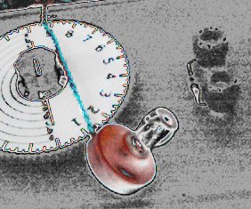
Here are a couple of shots of the box housing the variable capacitor, resistor, germanium diode and various binding posts. I took a bit of artistic licence with one of them.

If you build one of these I would like to know your results. Just post a comment here to that effect. I am particuarly interested in knowing how this design functions outside of the city. How many stations will it receive in a non-metro environment?
Also, if you have any questions about the design feel welcome to post them here.
Frankly, I am looking forward to spring so I can put away my winter projects and get back to gardening.
