What’s Happening

EmetteJep:

Thanks for your comment. I hope to post more but I am not sure when that will be. I have more insect photos waiting in the wings.

Lately I have been experimenting with efficient twig-fueled cooking stoves. I am very pleased with the results. Anyone interested can find what I did by doing a search on “rocket stoves”.

I have also been experimenting with regenerative radios, trying to find the one that uses the least power and fewest number of active devices (read: “transistors”) yet performs with sensitivity, selectivity, stability and covering a wide tuning range that includes short wave as well as AM broadcast. Someday I may publish my results. So far, it seems to me that three transistors are the minimum needed for a practical radio. I have been able to get one to run a long time on the power left in a battery that, for other purposes, is essentially dead.

From my organic garden I have been eating strawberries. Also: peppermint, curly dock, dandelion leaves, wild grape twigs and leaves, lambsquarters, winter savory, sorrel, garlic chives, common chives, wild lettuce and green onions. I typically collect a bowl full of an assortment of the above, wash it, chop it up fine, mix it with a bit of mayo, and eat it with biscuits, along with a tea from roasted dandelion roots.

I also love poke. It is very tender and has a delicate flavor. I do not include it in the above mix because it needs to be boiled twice before eating (or so I have heard; being one never to doubt authority, I always boil my poke twice).

I have a potato plant I transplanted when it volunteered in an inconvenient spot. Sweet potato slips are sprouting in the kitchen window. I also have carrots raising their heads in the garden. Carrots are all I deliberately started from seed this year (so far). They are slow growers, but I am faithfully keeping them watered and weeded.

I recently dumped a good bit of compost on the raised bed garden. The compost came from worm bins kept in the basement and an outside compost pile.

I still collect rainwater and filter it with a slow sand filter. I use the filtered water to hydrate the basement worm bins. I use unfiltered water to hydrate the outside bins and keep the seedlings from wilting.

I am still eating last years’ sour kraut from a jar in the refrigerator. It has been several months since I checked what is growing in the crocks kept in the basement. Reluctance to look comes from a little fear about what I might find.

I have not baked sour-dough bread for a while but I know how easy it is to create another starter from whole wheat flower should I ever need to.

I recently learned that the secret to soft biscuits is adding sugar to the dough.

I have not used the solar oven yet this year, mostly due to a sparsity of sunny days. It looks like summer is about to put an end to our rainy season soon, though.

It has been a good spring for wild mushrooms, but I have not found any that I could identify well enough to eat.

I am still convinced we need to take a serious look at true socialism. Obamanomics, the hysteria of media lick-spittles aside, is not socialism.

I might take up oil painting again soon. I did that a bit a very long time ago but have some new ideas about mixing paint that I want to try.

As you see, I keep very busy. Blogging frequently sits on the back burner. Thanks, again, for your interest.

Curlydock

First Multi-Mirror Solar Oven Simulations

by Curlydock
Nov 27, 2007

nov1039a.jpg

Results published in previous posts increased confidence in my solar oven simulation program. Those tests were confined to the single-mirror configuration. By keeping things simple, results were intuitively judged. Now it gets more interesting as we encounter kaleidoscopic multi-mirror configurations with results that may challenge intuition but that are, nevertheless, we hope, still accurate.

The number of variables that define the problem make closed form expression prohibitive, at least for me. Thus, my use of simulation.

HERE IS A LIST OF THOSE VARIABLES:

The oven seems simple enough in that it is composed of two sets of hinged mirrors and a sphere called a “bounding sphere” that stands for the oven cavity. The oven cavity is the part of the oven that gets hot enough to cook food. It is constructed like a small green house, but we need not concern ourself with those details.

The bounding sphere is all we need to know about the oven cavity. The center of the sphere gives the CAVITY LOCATION in EXTENSION and ELEVATION from the “origin”, the lowest point on the vertical R1-R2 hinge. The cavity location is always in the bisecting plane of the oven’s bilateral symmetry.

The radius of that sphere gives the SIZE OF THE CAVITY. Now, to make results easier to compare across simulations, I have normalized all units of distance to the diameter of the oven cavity. So, instead of inches, feet, meters, etc, all lengths are in units of cavity diameters.

I have named the four mirrors of concern: R1, R2, R3 and R4. Hinged on a vertical axis are R1 and R2. R3 and R4 are hinged horizontally. So, we have the two angles: R1–R2 ANGLE and R3–R4 ANGLE.

We will also be concerned with where the sun is in respect to our oven, so we have: SOLAR ALTITUDE ANGLE or elevation; zero degrees on horizon and 90.0 degrees at zenith, and SOLAR AZIMUTH ANGLE. In all runs I presently contemplate, the azimuth will not change, confining the sun to the plane that bisects the symmetry of the oven.

We also have to be concerned with R1 WIDTH and R1 HEIGHT. R2 is always identical to R1 in width and height.

Since R3 and R4 are hinged horizontally, it is confusing to speak of their width and height, so I define the dimension R4 RATIO, the length of the horizontal hinge, as a portion of the opening of R1-R2.

R3 is always parallel to, or in the plane of, the horizon. R1-R2 sits on R3 like an open book with the bottom two corners on the axis of the R3-R4 hinge. Because of this configuration, the reflective part of R3 will always be a triangle with size and shape determined by the width of R1, R2 and the R1-R2 angle. The other mirrors are always square or rectangular.

R4 EXTENSION is how far R4 extends from the horizontal hinge.

Also an input variable is the QUANTITY OF REFLECTIVE PLANES. I can consider four possibilities: R3 only; R1 and R2; R1, R2 and R3; as well as all four mirrors.

I think that about covers the input variables. So far I have not concerned myself with losses based on reflective angles, surface imperfections, convection, conduction, mass, re-radiation, transmission distances, imperfect insulation, etc.

OUTPUT

What we get for output is the amount of idealized SOLAR FLUX GAIN on the oven cavity over what the cavity would have gotten directly from the sun without any concentration. This is not a temperature; it is a ratio. The minimum value will always be 1.0 unless the cavity is in shadow or blocked from direct rays, where the value could fall to zero. The maximum value depends on all the inputs.

Because of the large quantity of possible combinations of input variables, I must find a way to lock some of them down so they can be temporarily ignored. That will simplify the problem and help us make sense of where we are in our journey to the “perfect” design. I do not know if there can ever be a proof that a particular design is the best possible one. There might always be a combination of inputs hitherto unconsidered that will yield a greater flux gain than what we thought was the best. If there is such a proof, a bigger brain than my own will need to find it.

That is why I am willing to share my program listing with anyone who is interested and who agrees to keep my program or any derived from it in the public domain, not for profit.

I am also willing to do runs for others who would like to see particular results of inputs meaningful to them. Perhaps they have built an oven or two and want to see what the simulation says about comparative performance. If you are interested, just leave your request in the comments section and I may publish my response or run results in a future post.

Next, some multi-mirror runs:

For the time being I will keep R1-R2 angle at 60.0 degrees. The decision is arbitrarily based on the fact that an oven I built uses that angle. In the long run, there may be a better angle.

Also, for now I keep the width of R1 at 4.0 cavity diameters. I do that because prior runs with R3-only seemed to result in 4.0 as the optimum size for the side of R3, given the R1-R2 angle = 60.0 degrees. The length of a side of R3 is the same as the width of R1 (and R2). Lastly, to start, I make the height of R1 equal to its width.

nov1029a.jpg

Chart “nov1029a” shows the effect of cavity extension on flux gain where only R1 and R2 are in play. For these inputs, the best value seems to be 1.4, but it depends on the angle of the sun. By this chart, for sun angles higher than about 40.0 degrees we might want to make the cavity extension less than 1.4 cavity diameters.

Next, keeping cavity extension at 1.4 and everything else the same, we do four runs, one for each of four different heights of R1-R2. That results in chart “nov1030” where
red (1) = 4.0
green (2) = 6.0
blue (3) = 8.0
black (4) = 10.0
cavity diameters.

nov1030a.jpg

We see gains increasing at higher sun angles as the height of R1-R2 increases. The gain increment decreases so returns are diminishing. At this point I will make the compromise of R1-R2 height = 6.0 and keep that for the next set of runs.

I cannot resist the temptation to add more mirrors at this point. Chart “nov1032” run (1) is a repeat of “nov1030” run (2), for reference. It looks different because the vertical axis of the chart is re-calibrated to cover higher gains.

nov1032a.jpg

Note the gain still peaks at about 6.0. That gain makes sense when you consider that two mirrors at a 60.0 degree angle would allow the sun to see six images of the cavity. Run (1) is only with R1 and R2 in play.

For run (2) I merely add reflector R3 to the play, and the results show a significant increase in gain. If we consider that R3 would double 6 images to 12, the gain seen of about 9.0 makes sense, considering some of the images will be partially obscured.

Now we take a lesson from a prior post when we were testing with only R3 and learned that it is best to elevate the cavity somewhat over R3. We do just that in run (3) and see that the gain is even closer to 12.0. Supposedly, the reason is that the images are less obscured when the cavity is elevated.

In run (4) I put R4 in play and made R4 the same size and shape of R1 and R2. It is a handy size if the oven is collapsible and you stack the reflectors for storage. The solar flux gain reached 14.0. One might worry that the simulation is malfunctioning because the flux gain is below 1.0 for very low angles of the sun. More thought reveals that at these low solar angles the cavity and lower part of the oven are in the shadow of R4, so one’s confidence in the program rebounds.

Is this the best design? I doubt it. Only more testing can tell, I guess. At least, it is a benchmark for measuring more attempts.

In a future post I can make the input variables conform to the oven I have actually constructed and see what the simulation says. I will be able to compare a real oven with this benchmark and tell what changes might make it better or worse without getting my hands dirty (not meaning to disparage getting one’s hands dirty).

Last Single-Mirror Solar Oven Simulation Test

by Curlydock
Nov 24, 2007

In my previous couple of posts I showed some of the results of tests of a program I wrote to simulate what I call a “kaleidoscopic” type solar oven. In earlier posts I detail the actual oven I use to bake bread. I wanted to see how to build a better oven of this type, so I wrote the simulation for ray-tracing various reflector sizes, shapes, quantities and configurations.

This post will cover what I hope is the last of the one-reflector tests. I wish to begin tests of two-mirror simulations in the next post.

nov1026a.jpg

Graph “nov1026a” shows the results of five runs with a single equilateral triangular reflector in the plane of the horizon. That reflector I frequently refer to as “R3”. Five sweeps of the sun from zero degrees (horizon) to 90 degrees (zenith) are shown, one sweep for each size of R3. The sides are all equal and are measured in cavity diameters. The smallest R3 is 2.0 and the largest is 8.0 cavity diameters on a side. The cavity bounding sphere is represented by the ball that is aways in the corner farthest from the sun when the sun is on the horizon.

Observe that the gain never exceeds 2.0 and never falls below 1.0. This is consistent with my expectations of what happens with only one mirror and increases my confidence in the simulator.

Rule 1026a

Also observe that the increment of improvement in gain decreases as R3 gets larger. Large mirrors increase the gain when the sun is at lower angles but the reflector has to get perhaps impractically large to produce these gains. At solar angles above about 20.0 degrees, it hardly seems worth having a floor reflector larger than 4.0 cavity diameters on a side. This is more than my prejudice up until now, which was that 3.0 cavity diameters on a side was the practical limit. The actual oven I made has only 3.0. So, the next time I build one of these ovens I will probably go with 4.0. It depends on what else we learn when more reflectors are in play.

“Rule 1026a” is, then: the triangular reflector always parallel with the plane of the horizon, that is the one the cavity is above, should be sized to about 4.0 cavity diameters on a side, physical practicality permitting, and probably not less than 3.0.

Now I combine this rule with rule 1010a from the previous post, which said the cavity should be elevated. That results in chart “1027a”:

nov1027a.jpg

For this run I kept the mirror sized to 8.0 cavity diameters on a side and elevated the bottom of the cavity from just touching R3 to where the bottom of the cavity is 0.5 cavity diameters over R3. Otherwise the run and chart calibration are the same.

Again, the gain never exceeds 2.0 and never falls below 1.0, which is good.

Also note that elevating the cavity improves gain when the sun is at higher angles. This is consistent with what we learned in the prior post and was to be expected. The simulation still seems to work. For this configuration, with the cavity elevated, the range of sun angles with the maximum gain of 2.0 is much larger.

In a prior post I expressed some doubt about whether the simulation was following the ray trace through an arbitrary number of reflections or breaking off too soon. I later discovered that was indeed a problem. But it only affected simulations of more than one mirror, none of which I had published yet. I fixed the bug and am now confident that I am ready to do multi-mirror tests. In the next post we will see some results using two reflectors. Those reflectors are the ones I have named “R1” and “R2” in prior posts. They are linked by a vertical hinge and open like a book over the plane of R3. R3 will be put aside while we consider only R1 and R2 and will return probably much later when three-mirror tests begin.

More Elementary Tests of a Solar Oven Simulation

by Curlydock

Nov 16, 2007

In the prior post I introduced a test of the simulation using only one plane of the “kaleidoscopic” type solar oven. So far, we have seen the bounding sphere of the oven cavity positioned over one triangular concentrator. That concentrator corresponds to the R3 reflector mentioned in other posts describing an actual oven that I have been using. The R3 reflector is in the plane that appears to be parallel with the earth’s surface and the cavity assembly rests on R3. In later posts we will be considering the effect of the other reflectors: R1, R2 and R4. This post is confined to more implications of the R3 reflector.

Diagrams “nov1007” and “nov1008” illustrate the oven cavity bounding sphere positioned at two different levels over the triangular reflector.

nov1007a.jpg nov1008

The red dots represent the absorption of a light ray on the surface of the bounding sphere. The blue dots represent rays reflected from the surface of the mirror that do not intercept the cavity. The shadow of the cavity can be seen on the mirror. The other dark spot on the mirror is that portion of the mirror where rays are reflected that do intercept the cavity.

This Test

The present question is how the height above the mirror affects the amount of solar flux gain the cavity will receive as the sun sweeps over an altitude angle from zero degrees on the horizon to 90 degrees at the zenith.

nov1010a.jpg

Diagram “nov1010” shows the result of four simulated solar sweeps, one for each of four different heights of the oven cavity above mirror R3.

On Units

Unless otherwise noted in these posts, the units of distance measurement will be cavity diameters. I think that is more interesting and informative than using yards or meters, etc. So, no matter what the radius of the cavity is in feet, centimeters, inches or any other unit, it is always 0.5 in cavity diameters. When the cavity rests on the mirror the center of the cavity will be 0.5 cavity diameters from the surface. The lowest point on the cavity, in that case, will be zero cavity diameters from the mirror.

The triangular mirror, R3, seen in the above illustrations and used in this particular post, is equilateral and 3.0 cavity diameters on a side. The cavity CENTER heights used to generate the data for the chart “nov1010” are 0.5 (red), 1.5 (green), 2.5 (blue) and 3.5 (black) cavity diameters. There is one color coded sun altitude sweep for each cavity placement.

The Solar Sweeps

These “altitude sweeps” are not the natural movements of the sun, so don’t be confused. The sweeps begin at the lowest point on the horizon and end at the highest point in the sky, or the zenith, at 90 degrees. The point on the horizon, zero degrees, where the sweep begins, is always in a vertical plane that bisects an angle of the triangular reflector.

The reason for this type of sweep is to see how the more complicated mirror arrangements respond to different solar angles, all of which keep the sun in the plane that bisects the symmetry of the concentrator arrangement. The purpose was to have a standardized sweep with which to compare different arrangements under any solar angle that might happen no matter what the season, location on the earth, or time of day, given that one could always adjust the oven so the sun is in that bisecting plane. Such an adjustment would not change the fact that R3 is in the plane of the horizon; it would merely rotate R3 in that plane. The tests to see how the simulated oven responds to a natural solar transit will probably be some of the last tests.

Rule 1010a

Now back to chart “nov1010”.

Note that when cavity height is lowest, 0.5, which corresponds to touching the mirror, the gain never reaches the greater levels it does when the cavity is elevated from the mirror. This is the reason for placing the inverted glass bowl underneath the oven cavity assembly, as seen in my prior posts detailing an actual solar oven. The lower bowl elevates the whole assembly a bit. I was never quite sure just how much it should be elevated but now it seems my simulations may help to determine this.

So, Rule 1010a for building kaleidoscopic solar ovens is: elevate the cavity over the mirror that is parallel to the plane of the horizon instead of letting it rest on it.

Next, we see just how much elevation is best. The above graphs suggest that the best cavity elevation will depend on the solar altitude. The angle of the sun is constantly changing; so, if we can figure out a way to easily adjust the cavity elevation about every twenty minutes, that would optimize flux gain at all times. Such a rig might be more complicated than the extra flux gain is worth, however.

Diagram “rule1010a”, seen below, might be used in the design and operation of a one-triangular reflector solar oven with an equilateral shaped mirror three cavity diameters on a side. It probably would not work for baking because the flux gain would never exceed 2.0. It might be useful for proofing bread dough or keeping a plate warm. It might also apply to ovens with more reflectors, but we have to wait to see what more tests produce to be sure.

rule1010a.jpg

This diagram allows us to determine the best cavity height above the reflecting plane for any given altitude angle of the sun. I gathered the data for the diagram from repeated runs with the simulation program. That these curves seem to make sense to me reinforces my confidence in the accuracy of the program so far (no guarantee, of course).

The runs show rather broad peaks. That suggests that a particular cavity elevation would work well for a wide range of solar angles without need to re-adjust the height. For that reason, the diagram “rule1010a” shows a region instead of a line. The acceptable region is in yellow-green between two limiting lines. The limiting lines represent the points where the solar flux gain has dropped to 0.9 times the peak value seen in the sweep. The graph seems to indicate that for solar angles below about 25 degrees there is no need to elevate the cavity at all. The flux gain might be very low, but elevating the cavity will not help.

How to Apply Rule 1010a

Here is an example of the use of diagram “rule1010a”:

Suppose the sun is at 70.0 degrees above the horizon. Find 70.0 degrees on the horizontal axis of the chart. Follow the vertical from 70 degrees up until it just reaches the green region (the first limiting line). Follow the horizontal from that point to read the cavity height. That yields about 0.70 cavity diameters.

Continue on the 70.0 degree vertical until the green region just ends (on the other limiting line). Following the horizontal from that point yields about 2.9 cavity diameters.

Therefore, the maximum gain will be when the BOTTOM (not the center) of the cavity is between 0.70 and 2.9 cavity diameters from the surface of mirror R3.

If the cavity is 12.0 inches in diameter then 0.70 cavity diameters represents 0.70 X 12.0 = 8.4 inches. Likewise, 2.9 cavity diameters X 12.0 inches per cavity diameter = 34.8 inches. At these points the gain will be about 9/10 what it would be at the peak.

To find the height corresponding to the actual peak, you can use the average. In this case, the average cavity height is (0.70 + 2.9) / 2.0 = 1.8 cavity diameters, and 1.8 X 12.0 = 21.6 inches.

In the morning and evening hours the sun is not so high and the cavity will not need so much elevation. Even if the cavity elevation is not optimum, the losses will not make the oven useless, it will probably just take a little longer to cook something. Also, when we start adding the other reflectors R1, R2 and R4, the gain will be considerably beyond 2.0, so some small maladjustments will be even less of a problem.

Initial Test of Solar Oven Simulation

by Curlydock
Nov 15, 2007

The diagram labeled “nov1002” displays a rudimentary test of my solar oven simulator. From this I hope to begin to see if the program is behaving correctly.

nov1002a.jpg

The oven cavity is seen as a ball above a triangular mirror.

A cross section of the solar flux is seen in yellow above right.

Any ray absorbed by the cavity is drawn in red. This could be either a ray directly from the sun or a ray reflected from the triangular mirror.

A ray reflected from the mirror that is not absorbed by the cavity is drawn as a short light blue vector. Any time a vector is drawn, the direction is indicated by the small ball at the end, which could be interpreted as an arrow head.

To reduce clutter in the diagram, the rays reflected and lost to space are drawn very short. They appear as a sort of light blue haze over the triangular reflector. You can see the “shadow” of the cavity on the mirror. Rays that neither hit the cavity nor the reflector are not drawn at all.

The program calculated the solar flux gain in this case to be 1.974359. This means that the cavity received almost twice as much solar radiation as it would have without any reflector at all. This is precisely what I would expect. The flux received by the cavity directly is doubled by the presence and proper placement of the mirror. The cavity would “see” two suns: one directly and the other reflected. Reciprocally, the sun would “see” two cavities, also one direct and one reflected. The analytical solar flux gain is two.

The theoretical flux gain without any reflector would be exactly one. That would be the minimum ever seen. Any properly directed reflections will increase that. The flux gain is calculated by dividing the quantity of rays absorbed with mirror concentrators in place by the quantity that would be absorbed directly from the sun when there are no mirrors. The simulation counts the rays and calculates the gain.
To see the importance of mirror orientation, we next consider what happens when the sun is at different angles, everything else remaining the same.

nov1003a.jpg

Diagram nov1003 shows how the flux gain drops to nearly unity when the sun is at a very low angle. The reason is that the triangular mirror is not of infinite extent. If it could be made large enough, we could get our gain back up to two. Thus the physical trade-off for the solar concentrator with the sun at small angles to the surface.

nov1004a.jpg

Diagram nov1004 shows the other extreme. Here, the sun is nearly at the zenith, but again the gain has dropped to nearly unity. This time the reason is that the cavity obscures the sun’s reflection. Where the cavity would “see” the sun it now only sees itself. The sun can only see the direct image of the cavity. The reflected image of the cavity is mostly hidden from the sun by the cavity itself.

These preliminary results continue to indicate that the simulation is correct.

Next, we can have the simulation sweep the solar altitude angle from zero degrees (on the horizon) to 90 degrees (at the zenith) and graph the flux gain against the solar angle. The triangular reflector is in the horizontal plane and therefore parallel with the horizon.

nov1005a.jpg

Diagram nov1005 shows the results of just such a sweep. We see the flux gain peaks at 2.0 broadly when the sun is around a 50.0 degree angle and falls to unity when the angle of the sun is either much more or much less than that.

In conclusion, the program I wrote to simulate some types of solar ovens seems to be working so far. I do still have reservations. There is more testing to do.

In future posts I hope to show the results of adding more reflecting flux concentrators. The flux gain will go up much more quickly with each added reflective plane as each added reflector exponentially increases the number of images (as in a kaleidoscope) while the increase in the number of mirrors is only linear. But limitations due to image obscuration, as we have already seen here, will subtract from the advantage of adding more reflectors, producing diminishing returns.

Some factors that affect real physics of multiple reflections I am going to ignore. I feel they would add a great deal of complexity without proportionally increasing the accuracy, at least for my purposes.

One of these factors is that every time a light beam is reflected, there is some loss. The amount of loss depends upon the angle of incidence. In my program, so far, this type of loss is not deliberately encoded. I assume no such losses.

Another factor is that no real reflector is perfect. Imperfect reflective surfaces will throw the light ray off at a non-ideal angle. Nor do I try to account for this effect.

Another factor is that I have some doubt about whether my program, as it is currently written, will ray-trace beyond about 4 or 5 reflections. I am not sure if this is true or why it happens if it does occur. I am keeping a look out for the effect but am not letting this doubt stop me from reaching for some results.

There may be other factors that have escaped my wildest dreams; who knows?

This work I put in the public domain for purposes of information and I do not claim it is perfect and suitable for just any application. If you are interested in seeing the listing, I am willing to share it. I can post it later.

Kaleidoscopic Solar Oven Temperature vs Time

by Curlydock
Nov. 13, 2007

In my previous post, on September 27, 2007, I went into detail describing the “Kaleidoscopic” type of solar oven that I have been using to bake bread.

image 93

Now I post the time versus temperature for an actual bread baking episode. The episode occurred in Jefferson County, Kentucky, USA, on a day in October, 2007. There had been a recent rain and the cloudless sky was unusually clear and free of haze. Starting at 10:55 AM EST, the bread baked to completion in about an hour. The maximum temperature recorded, between the black lid and top glass bowl, was 320 F (160 C). Just as I removed the bread, I saw the temperature was 325 F and probably still climbing. The ambient temperature was 64 F at the beginning and 70 F at the end.

The results are tabulated and graphed in the next image:

solar_oven_time_temp.jpg

__Time____Ambient______Oven________Note___________

10:55 AM ___ 64 F ___ not recorded ___ start baking

11:05 AM ___ 64 F ___ 240 F (116 C)

11:15 AM ___ 64 F ___ 275 F

11:20 AM ___ 66 F ___ 280 F (138 C)

11:30 AM ___ 68 F ___ 290 F

11:34 AM ___ 68 F ___ 300 F (140 C)

11:44 AM ___ 69 F ___ 308 F

11:56 AM ___ 70 F ___ 320 F (160 C) ___ condensation seen

12:06 AM ___ 70 F ___ 320 F ___ good odor, end baking

The optimum design for this type of oven is a fascinating problem. I wonder if 60 degrees is the best angle for the vertical axis and what the best sizes and proportions are for the reflecting panels. I am pretty sure it would be pointless to have the width of the vertically hinged panels be either more or less than three times the diameter of the oven cavity, for example. But I would like to have some way to test these personal prejudices.

To that end, I have given in to the temptation to do a detailed theoretical analysis. My way of doing this is to write a computer program that uses something like “ray tracing” to simulate the oven, allowing me to more easily see how different configurations affect the solar flux concentration. That program is pretty much finished and I hope to post some of the results in the near future.

Kaleidoscopic Solar Oven / Cooker

by Curlydock

One of my earliest installments dealt with the theory of the best angle to use with the reflecting planes of the solar concentrators of the Box-type solar oven. Since then, I have come to prefer what I call a “Kaleidoscopic” type solar oven.

I feel I have many reasons for this preference, but the most important is simplicity or ease of construction. Roughly speaking, the 3-D description of a Box-type oven takes about 20 vertexes and 32 lines. For the Kaleidoscopic type, it is 8 vertexes and 11 lines. So the Box type is about three times more complicated than the Kaleidoscopic type.

image 92

Image 92 shows the Kaleidoscopic oven I used to bake many loaves of genuine sourdough bread over this past summer.

image 91

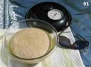
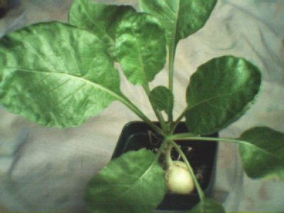
Image 91 shows a not-fully-risen loaf before baking. I consider it fully risen when the top of the loaf reaches the top of the bowl. The bread bakes in the oven-proof glass bowl which sits in the oven cavity. The cavity is detailed later.

image 82

image 83

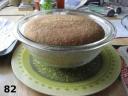
Images 82 and 83 show a finished loaf.

image 89

Image 89 looks into the front of my Kaleidoscopic oven. Most of the essential parts are seen. Missing is the glass bowl that would sit inverted over the top of the black lid. The oven cavity is shown in position and ready to receive the bowl of dough.

The reflective concentrators are in four planes. Two that I will call R1 and R2 form a vertically hinged unit that opens like a book and sits at a 60 degree angle. The hinge for R1 and R2 is made with strapping tape. The oven cavity just touches R1 and R2 and sits on R3, which is a separate unit the shape of a triangle.

The R3 angles are all 60 degrees and the length of each side is three times the diameter of the oven cavity. R1 and R2 are as wide as the sides of R3 and considerably taller than that.

R4 is also a separate piece and extends from the open edge of R3 as if it were hinged horizontally to R3. It could be permanently hinged but I feel there is no need for it. A pole pivots from the outer edge of R4 and fixes on the ground. It is used to set the angle of R4 so that the oven cavity is the brightest you can make it. If the wind is not blowing, gravity and the angle adjustment pole will keep R4 in place.

If there is wind, then I fasten all the sail-away reflective panels to the table with shoestrings. The cardboard from which R1, R2 and R4 are made is reinforced along bottom edges with narrow wood strips and package sealing tape. The shoestrings go through holes punched in the cardboard, around the wood strips, and through the mesh of the table top.

The weight of the oven cavity keeps R3 in place.

When the wind is very strong I use sandbags to hold down the table legs.

Here is a diagram comparing the Box and Kaleidoscopic type solar cooker / ovens and labeling of the concentrator panels I have been describing:

oven types diagram

The Box type has only one side glazed. That is the side where the solar flux enters the box. The other five sides have to be well insulated to keep the heat in. The maximum reachable temperature will depend a lot on the effectiveness of this insulation and the quality of box construction.

The Kaleidoscopic type does away with this particular need altogether by making all sides glazed. So, solar flux would enter all around the oven cavity, in theory. In actuality, this will not be perfect. The reasons have to do with the positioning of the oven cavity among the reflecting walls. Some positions are better than others.

Here is a detailed semi-exploded diagram of the oven cavity:

oven cavity diagram

The oven cavity works like a green house to trap the heat from the focused solar flux. The ideal would be a series of concentric spheres. The outermost sphere is transparent glazing that passes light. The next sphere is an insulating jacket to keep the heat, for which a vacuum would be best but air is easier. The next inner sphere is flat black metal which absorbs light and converts it to heat. This heat ideally accumulates in the central sphere where the food cooks in its container.

The ideal is approximated here by the use of oven proof glass bowls and a stainless steel metal mixing bowl.

The outermost sphere consists of two glass bowls: (1) is inverted on top and (4) completes the bottom half.

The insulating air jacket is made by suspending the metal radiation absorber bowl (6) on a ring (7) cut from a double layer of heavy corrugated cardboard. The ring rests on the lip of outer glass bowl (4). The lip of the metal bowl (6) makes a snug fit in the ring (7) so that the metal bowl will not fall through. The metal absorber does not touch the outer bowls anywhere. It only touches the cardboard ring. The ring and air jacket are poor conductors of heat. They confine most of the heat to the cooking area.

The metal radiation absorber bowl is a stainless steel mixing bowl painted flat black on the outside with the kind of paint that withstands heat, or the paint you would use on a charcoal grill. Let the paint dry, cure under heat and air out for several days before using it for cooking. You probably would not like paint flavored bread.

I was lucky in finding a black metal cooking pot lid (2) that just fits over the lip of (6) and rests on ring (7). There are cake or pie tins that might also work if painted black on the outside.

Bowl (3) holds the food or bread dough. It does not have to be transparent. I have been using oven proof glass but recently found a ceramic bowl that should also work. Another metal pot identical to (6) would fit snugly and maximize cooking space and thermal conduction to the food, but I have not tried that yet. In fact, I suppose you could do without (3) altogether by putting the food in the radiation absorber bowl (6). But, since (6) is not easy to get on and off ring (7) and the cardboard of (7) should not be washed or get wet, I decided to use another bowl to hold the food.

On my wish list is some kind of thin wire handle to make food bowl (3) easier to get in and out of metal bowl (6). The handle would need to quickly and easily connect and disconnect from the edge of the food bowl and not compromise the thermal seals around the edges.

The whole cavity needs to be somewhat elevated so I put it on a transparent pedestal made by inverting the smallest glass bowl (5) near a corner of the bottom reflector, R3.

Most of the glass bowls I found and purchased as a nested set. I think perhaps the largest, (4), was not part of that set and had to be separately purchased, but I am not sure.

Why Kaleidoscope

To study the effect of the focal positioning and the angle of R1 and R2, etc., I decided to research the geometrical and mathematical aspects of multiple reflections in mirrors. From that, I realized the kinship between kaleidoscopes and this type of solar cooker. The next pictures should make the relationship obvious.

Fascinating as it was, I thought it might take too long, so I did an empirical study with a scale model instead of the exacting thought experiments. I gathered some pieces salvaged from a broken mirror (never throw anything away), tape, and construction paper. Also, I borrowed a large bead from a trusting and tolerant friend.

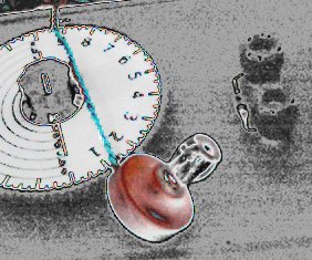
Image 74 is an overview of the apparatus:

image 74

The bead stands for the oven cavity or focus.

The mirrors that hinge on a vertical axis stand for reflecting planes or solar concentrators R1 and R2. R3, seen here on the bottom, will be moved in and out. R4 is not shown here but will be seen later.

image 57

image 60

image 61

image 62

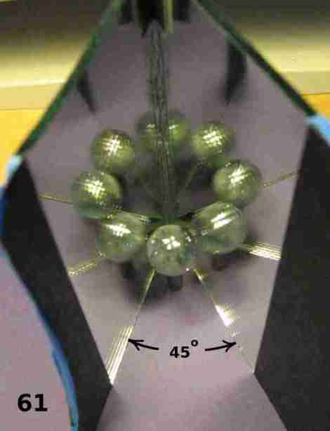
Images 57, 60, 61 and 62 show how the number of reflections of the bead increase as the angle between R1 and R2 decreases. This inverse relationship says to me that the narrower this angle the better as far as solar flux concentration.

Surely, the more images of the bead (oven cavity) the sun “sees” then the more solar flux will concentrate on the bead.

But there are several trade-offs.

As you can see, the ring of bead reflections gets gradually larger as the angle decreases. To compensate for this, the sizes or areas of R1 and R2 need to progressively increase. At some point R1 and R2 are too large and cumbersome.

image 63

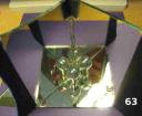
Image 63 shows how adding one more mirror, representing R3, doubles the number of bead images. Note how one of the images is lost because it is shadowed or hidden by the actual bead.

image 73

Image 73 shows how images are partially obscured when the bead is not elevated:

This is the reason that the oven chamber is elevated a bit by bowl (6).

image 72

Image 72 shows how the bead image count can be at least doubled yet again by adding the mirror that stands for R4. But, as the count and complexity of reflections increase, more and more images are obscured. There seems to be a threshold of diminishing returns.

image 66

Image 66 shows the concentrators at work. I used flash, which, I belatedly realized, is probably not good for a digital camera in a setup like this. Fortunately, perhaps most of the energy focused and dissipated on the bead instead of getting back into the camera lens.

If bead were bread, it baked.

How I Use the Kaleidoscopic Solar Oven

I use an angle of 60 degrees between R1 and R2. There may be a better angle. I have not tried others yet. I adjust the table orientation and the angle of R4 about once every 15 or 20 minutes. This needs to be done more often when the sun is high in the sky.

I frequently measure a temperature of 280 F between the top glaze bowl (1) and the lid (2), depending on the time of day. Morning hours, with the sun at a lower angle, seem to make the oven hotter than do the noon hours, probably because of the reflection obscuring effect already mentioned. Elevating the oven cavity even more when the sun is high in the sky might make the oven even hotter, but I have not needed to try that yet.

Either time of day works fine for baking my bread. The recipe for one loaf of sourdough calls for 45 minutes at 350 F in my conventional oven. I can bake 3/4 of that recipe in the Kaleidoscope solar oven in around 90 minutes. The crust browns nicely, especially on the top.

You might be tempted to let the finished bread cool just a little bit in the oven. But don’t do that. And don’t be fooled. The oven gets very hot. Be careful not to burn yourself.

While the oven is cooking, the moisture escapes as steam. As soon as the oven starts to cool, that moisture condenses on the lids and runs down to collect on the corrugated cardboard ring. The cardboard ring may dissolve if it gets wet. But, it can withstand the highest temperatures of the oven just fine. The high temperature helps keep the ring dry. As soon as I finish baking, I dump the bread on a rack to cool.

After a bit of practice, you can tell when the bread is finished baking by how it smells around the solar oven. Also, you will begin to see condensation on the inner side of glass bowl (1) when the bread is ready.

Outside of baking sourdough and cornbread, I have not yet cooked other things in this particular oven / cooker. I wonder if the condensation will be more of a problem if, for example, I make soup. I don’t know yet.

A Note on Construction Technique

Many instruct builders of these types of ovens to glue the aluminum foil to the cardboard with diluted white glue. I no longer do this.

I believe it is sufficient to bend the foil around the edges of the corrugated cardboard and fasten it in the reflective plane about every square foot using brass plated paper fasteners. Insert the fasteners through small holes prepared with a knife blade. These fasteners can be found where you get office supplies. They look like tacks with points that can be spread apart. This is much easier than working with glue. It is easy to repair.

But the main reason I do it this way is that the foil is easily removed from the cardboard when time comes to recycle them both. My red worms can eat the cardboard but the foil might not be good for them and would not be wanted in the vermicompost.

I do use white glue or carpenter’s glue to bond cardboard to cardboard where a panel needs more strength or a flap needs to be made rigid.

image 93

Insectary Plants and Beneficial Insects by Curlydock

My recent surge of interest in insectary plants and beneficial insects found me in the garden with my camera. I spent about an hour taking pictures of any insect I saw and noting the plant each insect was seemingly associated with.

I did this on September 8, 2007, in my small experimental urban organic garden located in Jefferson County, Kentucky, USA. These are a few of the pictures.

I am not expert at insect identification. If you think my guesses or any other data I give are not correct, please feel free to leave a comment with your own opinion.

To avoid the use of chemical poisons, I hope to eventually have enough of the right kind of insectary plants. The theory is that the right plants will attract the kinds of good insects that predate on the bad insects. Bad insects do bad things like chewing big holes in my broccoli leaves, for example.

I understand that one should not attempt to wipe out the bad bugs altogether. Enough of the bad bugs should exist to feed the good bugs so the good bugs will stay in the garden and not have to leave in search of a meal. While this is not mechanically efficient, an argument could be made that mechanical efficiency is not a sustainable way to relate to the environment.

One should seek the productive balance innate in stabilized diversity and then not sully that balance with pollution, poisons, and the exhaustion that comes from expectations of competitively efficient exponential growth. The correct balance can be productive enough to sustain the lives of farmers and those who depend on farmers for meals, were the world not obsessed with greed.

Since the good bugs burn a lot of energy in their hunt, they need the nectar and pollen of flowers to help sustain that energy. To that end, some plants are better than others at attracting good bugs. The shape of the blossom might help or hinder the access of a particular insect to the pollen and nectar the plant offers. Also, some plants can attract aphids or insects that are specific to that plant and will not harm garden plants but will provide meals for the good bugs. Not all plants bloom at the same time, so in a diversity at least one plant will always be supplying the good bugs with what they need. It is also possible that the wrong plant would attract bugs bad for the garden or host diseases also bad for the garden.

So, it can get complicated. I need to study hard to find the right combination of insectary plants to grow in or near my garden. On the bright side, the complexity of the study is deep enough to keep one interested for a whole lifetime. One need not study rocket science to keep from getting bored. How nature grows diversity will suffice.

bumblebee

Image 417 is perhaps a bumblebee. Some think it is, instead, a carpenter bee. They look a lot alike but I understand the abdomen of the carpenter bee is slick instead of hairy. This insect is beneficial because it pollinates flowers. The bee rests on the flower head of Garlic Chives (Allium tuberosum). The bee was so still I thought it might be dead or asleep. Or drunk? When I finally nudged it, it moved sluggishly but it never flew or even buzzed all the time I was there.

image 498

Image 498 shows what seems to be a different type and much smaller bee. This one is on a marigold blossom.

image 398

Image 398 shows what I believe is a soldier beetle called Pennsylvania Leatherwing (Chauliognathus pennsylvanicus). Many say it is beneficial but at least one said this insect’s value may be exaggerated. Even if it does not eat bad insects, at least it seems to be a good pollinator of Garlic Chives, for there were a lot of these soldier beetles there.

image 490

Image 490 may be a Green Bottle Fly, I am not sure. Green Blow Flies are supposedly associated with decaying flesh, but there were a lot of these really interested in the Garlic Chives. Nothing smelled dead.

image 437

Image 437 may be what is called a “Question Mark” butterfly, but I am not sure. It rested close to corn and beans.

image 460

Image 460 shows a wasp that repeatedly returned for a drink of water from the little watering hole. Many wasps are beneficial because they predate on bad bugs.

The watering hole is made of an overturned garbage can lid. I keep it replenished with water from the rain barrel. I change the water at most after every couple of days to keep mosquitoes from breeding in it and to keep it from stagnating. I had hoped the watering hole and an adjacent shelter hole would attract a toad, but I have not seen a toad yet. I did see a blue-tailed lizard not too far from the water, but that was much earlier in the year.

image 378

Image 378 shows, I believe, the eggs of a Leaf Footed Bug or Stink Bug. The eggs were attached underneath a leaf of broccoli. I did not see any adults this day, but I have seen them before. They have hind legs that are flattened like a spatula or leaf. Some of them may be beneficial, sucking on caterpillars of bad bugs. But I suspect the ones around here are only interested in sucking juice from the broccoli.

image 379

Image 379 shows a moth caterpillar that might be an “Inch Worm”. It has been feasting on the broccoli and a bad type. I hope someday I see a beneficial insect feasting on it.

image 383

Image 383 is a young, I think, type of Harlequin Bug. They also eat the broccoli.

image 433

Image 433 is a Garden Spider, (perhaps Argiope aurantia). I understand that these spiders need a source of water. This one was about 4 feet from the watering hole and very near the corn and beans. I believe spiders are, on balance, beneficial.

In conclusion, many insects could be seen in one hour in my organic garden. Some were beneficial and some were not. Many pollinators were seen. Many destructive insects were seen. I would like to see a lot more beneficial predators. I recently transplanted some Golden Rod to my garden. I found it on a farm in an adjacent county. I have heard that Golden Rod is a good insectary plant. That it aggravates hay fever and allergies is a bad rap and is not true, from what I have read. I plan to introduce more selected flowers in the future. When I planted the Garlic Chives (Allium tuberosum) I did it for food. I did not know it was an excellent insectary too, until I saw it in action.

Winter Window Garden

by Curlydock

Some months back, in November / December of 2006, I wrote several installments dealing with seedling identification. I sprouted seedlings and tried to keep a webcam record of them for future reference. The seedlings became spindly and were growing slowly because, I believe, of short winter days and little light.

I did not want to burn energy in lights and timers, so I left the mini-garden in the southern window to fend for itself. I did keep it watered with rain-water that had been slow-sand filtered. I also warmed the water a bit by storing a gallon or so of it by a furnace duct.

As the days got longer I noticed the plants began to grow more rapidly. A few weeks ago I harvested and ate a head and some leaves from the rapini. It was delicious.

Today, before I harvested and ate the radish I took some webcam shots of the radish and the chard. Someone frequently visits this blog looking for pictures of the plants. So, here are a few more plant pictures.

day 110 white hailstone radish

Above is the white hailstone radish. It has been 110 days since the seed was planted. Below is the rhubarb chard. It was planted 82 days ago.

Day 82 rhubarb chard

The pots they grow in are about 3 inches cubed. The potting medium in each is half peat moss and half my vermicompost. Each pot also has about 2 tablespoons of crushed eggshell.

The plants are very delicate. They don’t get strong breezes so their stems have not grown stiff. When I moved the chard to photograph it, it fell over. I propped it up a with a ball of tissue.

When I removed the tissue I noticed the tissue was damp, and the odor I cannot describe except to say it was heavenly.

Drinking in that odor of healthy organic compost in communion with the chard roots reminded me powerfully of what we have lost in our culture. This is the odor of a small organic farm. It is the odor many more of us should be familiar with. It is the odor more of us must become familiar with if there is to be a future for us on this planet.

This odor energizes an intuition of what is right and what is wrong. It puts me out of reach of the propoganda of pundits, thinktanks, preachers, bad teachers, blustering talk show bloviators, and all apologists for greed who seek to influence and control us. It puts my mind and heart on a firm foundation. Let them spin and grin, with their fingers crossed. I know which side I’m on. They won’t fool me again.

Simplest Radios

by Curlydock

The simplest radio

receivers require no batteries, gasoline, coal, oil, nuclear, wind, geothermal, tidal, or solar power.

And, they are indeed simple. Using them and building them out of parts found in the junkbox or scavanged from yard-sales will not hurt the planet and will not make Greedy Gates even richer.

I built this one for a recent experiment. It has only five electrical components. The only power it requires exists in the signal it receives. In our metro area (Louisville, Ky) in one afternoon I received eleven stations loud and clear. These transmitters were all local and within about a twelve mile radius. Their powers ranged between 500 watts and 50 Kilo-watts. The 500 watt station is roughly 5 miles away.

These radios are variously called crystal sets, crystal radios, or foxhole radios. In the “foxhole” variety, the home-made simplicity includes the signal detector, which is a razor blade and piece of pencil lead!

The All-Powerful Antenna

For this type of radio to work well, every consideration must be made to conserve the precious power that arrives in the signal. This typically requires a very long and high outdoor antenna and a good ground connection. This antenna is a wire between 30 and several hundred feet long. The ground connection can be a cold water pipe (but only if it is metal into the earth) or a metal rod or pipe driven 4 to eight feet or so into the earth. Good performance depends on a good ground connection and such connections are sometimes hard to come by. For safety, one should also install some kind of lightning arrestor and disconnect the radio during bad weather. Also, one should install the antenna well clear of power lines. All this may be difficult to impossible in a metro environment.

Until this experiment,
I believed crystal radios could not be made portable or operate effectively with an indoor antenna. Now I know otherwise. You still can’t stick it in a pocket, but you can easily carry the radio and antenna around while you listen to a station.

Given the appearance of the antenna, you would attract a lot of attention outside. Whether attracting attention is good or bad depends on you and your needs and the particular setting, I guess.

Anyway, here is a picture of the crystal set and antenna I built and used in this experiment:

crystal set used in experiment

It sits in the comfortable chair, for scale, next to the special loop antenna. The loop antenna has a 32-inch outside diameter. This installment is really about the antenna, because that is what made the radio able to receive as well as it does.

The antenna is not as heavy as it looks because the bulky part is cut from thick sheets of styrofoam insulation, which is mostly gas and therefore light. The rings are glued like a sandwich over the sector fingers, which were made of scrap pieces of a wall covering that resembles pressed fiber board (like some clip boards are made of). The antenna can easily be lifted from the pvc pipe support and carried around slung across your shoulder, all the while supplying signal to the radio.

Other materials can be used. In other versions, I used bamboo chopsticks taped in pairs on either side of wood popsicle sticks, creating the slot that the cable is woven through. I have also cut the whole ring and set of sectors and slots from large sheets of cardboard. To strengthen large diameters, you might want to use white glue or flour paste to build up several layers of cardboard. Use styrofoam, plastic, wood, cardboard, pvc pipe or plexiglass but keep the use of metal in the antenna to a bare minimum. Even the non-metal structure should be kept to the minimum needed for support of the wire. For example, if you use large sheets of cardboard, cut out the middle so that it is a ring instead of a disc. Discarding anything that is not needed in the viscintiy of the antenna will improve it’s quality. Ideally, if you can figure out a way to support the wire on nothing but air, more power to you (and to your radio)!

The weave of the cable is important. Here is a close up showing how this weave was accomplished on this antenna:The weave in the sector slots

This neat alternation is possible only with an odd number of sectors. Use 5, 9, or 11 sectors, but not 6, 10 or 12, etc. No, it is not numerology. I am not superstitious. Try it and see!

The reason for this weave is that it keeps the individual turns of wire separated from each other. The separation is needed because if the wires lay close together, as in a close-wound coil, something called capacitance will build up with each added turn to such a degree that it spoils the quality of the coil. I know it sounds like I am just pulling this out of my…, but, believe me, it’s true!

The wire

I used in the antenna was about 90 or 100 feet of cable from a spool labeled: “100-Ft. (30.4m) Telephone-Station Wire 8-con.(4 twisted pair) 24-Ga. Solid Color-coded.”

It was copper wire.

I first wound the whole antenna and then went back and cut each turn.

That can be done neatly if you cut all the cable on each side of one particular support slot but on only one side of the plane of the disk. That sounds complicated, but however you end up with a coil of eleven turns with one tap per turn and an extra tap for the odd end is ok with me.

The eight individual wires in these cuts were then cleaned of insulation and soldered together. The ends were then re-joined as they were before they were cut, along with a wire from this joint that terminated at a tap made of a tiny brass nail embedded in a piece of plexiglass. Each end of the original cable was treated the same way. Since the antenna has eleven turns, there are 12 taps.

Here is a close up of the taps:

eleven turns and twelve taps

The reason for all those taps is that it offers the most flexibility in choosing the way the antenna is connected to the other components.

The reason for connecting the eight individual wires in the cable in parallel for each turn is that the cable becomes a rough approximation of a special kind of wire called “litz” wire that is ideally used for this sort of purpose but is expensive and hard to come by. At the very least, wiring our telephone cable this way reduces resistive power losses by increasing the copper conductor cross section.

You could also use coaxial cable of the type for connecting between TV or FM antennas and their equipment. It doesn’t matter exactly what kind of coaxial cable as long as it has a large diameter and a good shield. Then, ignore the center conductor and use only the shield when you make your taps. The copper cross section in the shield is much more than that of the center conductor. You could connect the center conductor to the shield at each opportunity but it will probably not matter much. The signal will all want to flow in the shield anyway, due to something called the “skin effect”. No, I am not making this up.

Now is a good time to introduce

The schematic:
schematic for crystal radio
See the taps? There are two sub-circuits to connect, each having two alligator clips.

Where the variable capacitor is connected determines the tuning range. Select taps enclosing more turns to lower the minimum tuning frequency. Connect the capacitor across fewer turns to tune to higher frequencies. I have found the whole AM broadcast band is covered with two taps.

Where the germanium diode circuit is connected affects the selectivity, or the ability to tune one station at a time. It also affects signal loudness because the different taps affect what is called “impedance matching”. In addition, there is a transformer action, but the actual transformed output voltage will depend on the “Q” or bandwidth. The theory is complicated but fortunately the best tap points are easily found by trial and error (as long as you don’t have to keep cutting and soldering over and over again. That is the beauty of having each turn with a permanent tap.)

Generally, the radio works best when the detector circuit taps between a number of turns equal to about a third of the number of turns the capacitor is tapped between. But the best position can change if you change the type of detector or earphone.

Speaking of earphones,

the kind you get with just about any electronic equipment these days will not work. The earphone has to be a high-impedance type. A few places still sell them. If you can’t find one, look for an older telephone. Sometimes the receivers on them work passably well, indeed very well if you can find a matching transformer. Details about how to fix these sorts of problems can be found elsewhere on the Internet. Just do a search on “crystal set” or “crystal radio”. It is a remarkably popular topic.

Here are a couple of shots of the box housing the variable capacitor, resistor, germanium diode and various binding posts. I took a bit of artistic licence with one of them.

crystal radio

close up of crystal radio

If you build one of these I would like to know your results. Just post a comment here to that effect. I am particuarly interested in knowing how this design functions outside of the city. How many stations will it receive in a non-metro environment?

Also, if you have any questions about the design feel welcome to post them here.

Frankly, I am looking forward to spring so I can put away my winter projects and get back to gardening.