More Elementary Tests of a Solar Oven Simulation

by Curlydock

Nov 16, 2007

In the prior post I introduced a test of the simulation using only one plane of the “kaleidoscopic” type solar oven. So far, we have seen the bounding sphere of the oven cavity positioned over one triangular concentrator. That concentrator corresponds to the R3 reflector mentioned in other posts describing an actual oven that I have been using. The R3 reflector is in the plane that appears to be parallel with the earth’s surface and the cavity assembly rests on R3. In later posts we will be considering the effect of the other reflectors: R1, R2 and R4. This post is confined to more implications of the R3 reflector.

Diagrams “nov1007” and “nov1008” illustrate the oven cavity bounding sphere positioned at two different levels over the triangular reflector.

nov1007a.jpg nov1008

The red dots represent the absorption of a light ray on the surface of the bounding sphere. The blue dots represent rays reflected from the surface of the mirror that do not intercept the cavity. The shadow of the cavity can be seen on the mirror. The other dark spot on the mirror is that portion of the mirror where rays are reflected that do intercept the cavity.

This Test

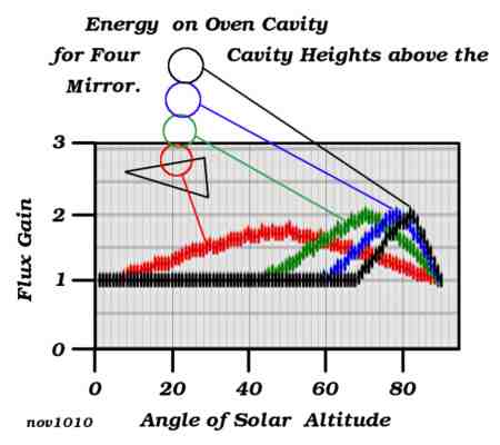
The present question is how the height above the mirror affects the amount of solar flux gain the cavity will receive as the sun sweeps over an altitude angle from zero degrees on the horizon to 90 degrees at the zenith.

nov1010a.jpg

Diagram “nov1010” shows the result of four simulated solar sweeps, one for each of four different heights of the oven cavity above mirror R3.

On Units

Unless otherwise noted in these posts, the units of distance measurement will be cavity diameters. I think that is more interesting and informative than using yards or meters, etc. So, no matter what the radius of the cavity is in feet, centimeters, inches or any other unit, it is always 0.5 in cavity diameters. When the cavity rests on the mirror the center of the cavity will be 0.5 cavity diameters from the surface. The lowest point on the cavity, in that case, will be zero cavity diameters from the mirror.

The triangular mirror, R3, seen in the above illustrations and used in this particular post, is equilateral and 3.0 cavity diameters on a side. The cavity CENTER heights used to generate the data for the chart “nov1010” are 0.5 (red), 1.5 (green), 2.5 (blue) and 3.5 (black) cavity diameters. There is one color coded sun altitude sweep for each cavity placement.

The Solar Sweeps

These “altitude sweeps” are not the natural movements of the sun, so don’t be confused. The sweeps begin at the lowest point on the horizon and end at the highest point in the sky, or the zenith, at 90 degrees. The point on the horizon, zero degrees, where the sweep begins, is always in a vertical plane that bisects an angle of the triangular reflector.

The reason for this type of sweep is to see how the more complicated mirror arrangements respond to different solar angles, all of which keep the sun in the plane that bisects the symmetry of the concentrator arrangement. The purpose was to have a standardized sweep with which to compare different arrangements under any solar angle that might happen no matter what the season, location on the earth, or time of day, given that one could always adjust the oven so the sun is in that bisecting plane. Such an adjustment would not change the fact that R3 is in the plane of the horizon; it would merely rotate R3 in that plane. The tests to see how the simulated oven responds to a natural solar transit will probably be some of the last tests.

Rule 1010a

Now back to chart “nov1010”.

Note that when cavity height is lowest, 0.5, which corresponds to touching the mirror, the gain never reaches the greater levels it does when the cavity is elevated from the mirror. This is the reason for placing the inverted glass bowl underneath the oven cavity assembly, as seen in my prior posts detailing an actual solar oven. The lower bowl elevates the whole assembly a bit. I was never quite sure just how much it should be elevated but now it seems my simulations may help to determine this.

So, Rule 1010a for building kaleidoscopic solar ovens is: elevate the cavity over the mirror that is parallel to the plane of the horizon instead of letting it rest on it.

Next, we see just how much elevation is best. The above graphs suggest that the best cavity elevation will depend on the solar altitude. The angle of the sun is constantly changing; so, if we can figure out a way to easily adjust the cavity elevation about every twenty minutes, that would optimize flux gain at all times. Such a rig might be more complicated than the extra flux gain is worth, however.

Diagram “rule1010a”, seen below, might be used in the design and operation of a one-triangular reflector solar oven with an equilateral shaped mirror three cavity diameters on a side. It probably would not work for baking because the flux gain would never exceed 2.0. It might be useful for proofing bread dough or keeping a plate warm. It might also apply to ovens with more reflectors, but we have to wait to see what more tests produce to be sure.

rule1010a.jpg

This diagram allows us to determine the best cavity height above the reflecting plane for any given altitude angle of the sun. I gathered the data for the diagram from repeated runs with the simulation program. That these curves seem to make sense to me reinforces my confidence in the accuracy of the program so far (no guarantee, of course).

The runs show rather broad peaks. That suggests that a particular cavity elevation would work well for a wide range of solar angles without need to re-adjust the height. For that reason, the diagram “rule1010a” shows a region instead of a line. The acceptable region is in yellow-green between two limiting lines. The limiting lines represent the points where the solar flux gain has dropped to 0.9 times the peak value seen in the sweep. The graph seems to indicate that for solar angles below about 25 degrees there is no need to elevate the cavity at all. The flux gain might be very low, but elevating the cavity will not help.

How to Apply Rule 1010a

Here is an example of the use of diagram “rule1010a”:

Suppose the sun is at 70.0 degrees above the horizon. Find 70.0 degrees on the horizontal axis of the chart. Follow the vertical from 70 degrees up until it just reaches the green region (the first limiting line). Follow the horizontal from that point to read the cavity height. That yields about 0.70 cavity diameters.

Continue on the 70.0 degree vertical until the green region just ends (on the other limiting line). Following the horizontal from that point yields about 2.9 cavity diameters.

Therefore, the maximum gain will be when the BOTTOM (not the center) of the cavity is between 0.70 and 2.9 cavity diameters from the surface of mirror R3.

If the cavity is 12.0 inches in diameter then 0.70 cavity diameters represents 0.70 X 12.0 = 8.4 inches. Likewise, 2.9 cavity diameters X 12.0 inches per cavity diameter = 34.8 inches. At these points the gain will be about 9/10 what it would be at the peak.

To find the height corresponding to the actual peak, you can use the average. In this case, the average cavity height is (0.70 + 2.9) / 2.0 = 1.8 cavity diameters, and 1.8 X 12.0 = 21.6 inches.

In the morning and evening hours the sun is not so high and the cavity will not need so much elevation. Even if the cavity elevation is not optimum, the losses will not make the oven useless, it will probably just take a little longer to cook something. Also, when we start adding the other reflectors R1, R2 and R4, the gain will be considerably beyond 2.0, so some small maladjustments will be even less of a problem.

Kaleidoscopic Solar Oven Temperature vs Time

by Curlydock
Nov. 13, 2007

In my previous post, on September 27, 2007, I went into detail describing the “Kaleidoscopic” type of solar oven that I have been using to bake bread.

image 93

Now I post the time versus temperature for an actual bread baking episode. The episode occurred in Jefferson County, Kentucky, USA, on a day in October, 2007. There had been a recent rain and the cloudless sky was unusually clear and free of haze. Starting at 10:55 AM EST, the bread baked to completion in about an hour. The maximum temperature recorded, between the black lid and top glass bowl, was 320 F (160 C). Just as I removed the bread, I saw the temperature was 325 F and probably still climbing. The ambient temperature was 64 F at the beginning and 70 F at the end.

The results are tabulated and graphed in the next image:

solar_oven_time_temp.jpg

__Time____Ambient______Oven________Note___________

10:55 AM ___ 64 F ___ not recorded ___ start baking

11:05 AM ___ 64 F ___ 240 F (116 C)

11:15 AM ___ 64 F ___ 275 F

11:20 AM ___ 66 F ___ 280 F (138 C)

11:30 AM ___ 68 F ___ 290 F

11:34 AM ___ 68 F ___ 300 F (140 C)

11:44 AM ___ 69 F ___ 308 F

11:56 AM ___ 70 F ___ 320 F (160 C) ___ condensation seen

12:06 AM ___ 70 F ___ 320 F ___ good odor, end baking

The optimum design for this type of oven is a fascinating problem. I wonder if 60 degrees is the best angle for the vertical axis and what the best sizes and proportions are for the reflecting panels. I am pretty sure it would be pointless to have the width of the vertically hinged panels be either more or less than three times the diameter of the oven cavity, for example. But I would like to have some way to test these personal prejudices.

To that end, I have given in to the temptation to do a detailed theoretical analysis. My way of doing this is to write a computer program that uses something like “ray tracing” to simulate the oven, allowing me to more easily see how different configurations affect the solar flux concentration. That program is pretty much finished and I hope to post some of the results in the near future.

Kaleidoscopic Solar Oven / Cooker

by Curlydock

One of my earliest installments dealt with the theory of the best angle to use with the reflecting planes of the solar concentrators of the Box-type solar oven. Since then, I have come to prefer what I call a “Kaleidoscopic” type solar oven.

I feel I have many reasons for this preference, but the most important is simplicity or ease of construction. Roughly speaking, the 3-D description of a Box-type oven takes about 20 vertexes and 32 lines. For the Kaleidoscopic type, it is 8 vertexes and 11 lines. So the Box type is about three times more complicated than the Kaleidoscopic type.

image 92

Image 92 shows the Kaleidoscopic oven I used to bake many loaves of genuine sourdough bread over this past summer.

image 91

Image 91 shows a not-fully-risen loaf before baking. I consider it fully risen when the top of the loaf reaches the top of the bowl. The bread bakes in the oven-proof glass bowl which sits in the oven cavity. The cavity is detailed later.

image 82

image 83

Images 82 and 83 show a finished loaf.

image 89

Image 89 looks into the front of my Kaleidoscopic oven. Most of the essential parts are seen. Missing is the glass bowl that would sit inverted over the top of the black lid. The oven cavity is shown in position and ready to receive the bowl of dough.

The reflective concentrators are in four planes. Two that I will call R1 and R2 form a vertically hinged unit that opens like a book and sits at a 60 degree angle. The hinge for R1 and R2 is made with strapping tape. The oven cavity just touches R1 and R2 and sits on R3, which is a separate unit the shape of a triangle.

The R3 angles are all 60 degrees and the length of each side is three times the diameter of the oven cavity. R1 and R2 are as wide as the sides of R3 and considerably taller than that.

R4 is also a separate piece and extends from the open edge of R3 as if it were hinged horizontally to R3. It could be permanently hinged but I feel there is no need for it. A pole pivots from the outer edge of R4 and fixes on the ground. It is used to set the angle of R4 so that the oven cavity is the brightest you can make it. If the wind is not blowing, gravity and the angle adjustment pole will keep R4 in place.

If there is wind, then I fasten all the sail-away reflective panels to the table with shoestrings. The cardboard from which R1, R2 and R4 are made is reinforced along bottom edges with narrow wood strips and package sealing tape. The shoestrings go through holes punched in the cardboard, around the wood strips, and through the mesh of the table top.

The weight of the oven cavity keeps R3 in place.

When the wind is very strong I use sandbags to hold down the table legs.

Here is a diagram comparing the Box and Kaleidoscopic type solar cooker / ovens and labeling of the concentrator panels I have been describing:

oven types diagram

The Box type has only one side glazed. That is the side where the solar flux enters the box. The other five sides have to be well insulated to keep the heat in. The maximum reachable temperature will depend a lot on the effectiveness of this insulation and the quality of box construction.

The Kaleidoscopic type does away with this particular need altogether by making all sides glazed. So, solar flux would enter all around the oven cavity, in theory. In actuality, this will not be perfect. The reasons have to do with the positioning of the oven cavity among the reflecting walls. Some positions are better than others.

Here is a detailed semi-exploded diagram of the oven cavity:

oven cavity diagram

The oven cavity works like a green house to trap the heat from the focused solar flux. The ideal would be a series of concentric spheres. The outermost sphere is transparent glazing that passes light. The next sphere is an insulating jacket to keep the heat, for which a vacuum would be best but air is easier. The next inner sphere is flat black metal which absorbs light and converts it to heat. This heat ideally accumulates in the central sphere where the food cooks in its container.

The ideal is approximated here by the use of oven proof glass bowls and a stainless steel metal mixing bowl.

The outermost sphere consists of two glass bowls: (1) is inverted on top and (4) completes the bottom half.

The insulating air jacket is made by suspending the metal radiation absorber bowl (6) on a ring (7) cut from a double layer of heavy corrugated cardboard. The ring rests on the lip of outer glass bowl (4). The lip of the metal bowl (6) makes a snug fit in the ring (7) so that the metal bowl will not fall through. The metal absorber does not touch the outer bowls anywhere. It only touches the cardboard ring. The ring and air jacket are poor conductors of heat. They confine most of the heat to the cooking area.

The metal radiation absorber bowl is a stainless steel mixing bowl painted flat black on the outside with the kind of paint that withstands heat, or the paint you would use on a charcoal grill. Let the paint dry, cure under heat and air out for several days before using it for cooking. You probably would not like paint flavored bread.

I was lucky in finding a black metal cooking pot lid (2) that just fits over the lip of (6) and rests on ring (7). There are cake or pie tins that might also work if painted black on the outside.

Bowl (3) holds the food or bread dough. It does not have to be transparent. I have been using oven proof glass but recently found a ceramic bowl that should also work. Another metal pot identical to (6) would fit snugly and maximize cooking space and thermal conduction to the food, but I have not tried that yet. In fact, I suppose you could do without (3) altogether by putting the food in the radiation absorber bowl (6). But, since (6) is not easy to get on and off ring (7) and the cardboard of (7) should not be washed or get wet, I decided to use another bowl to hold the food.

On my wish list is some kind of thin wire handle to make food bowl (3) easier to get in and out of metal bowl (6). The handle would need to quickly and easily connect and disconnect from the edge of the food bowl and not compromise the thermal seals around the edges.

The whole cavity needs to be somewhat elevated so I put it on a transparent pedestal made by inverting the smallest glass bowl (5) near a corner of the bottom reflector, R3.

Most of the glass bowls I found and purchased as a nested set. I think perhaps the largest, (4), was not part of that set and had to be separately purchased, but I am not sure.

Why Kaleidoscope

To study the effect of the focal positioning and the angle of R1 and R2, etc., I decided to research the geometrical and mathematical aspects of multiple reflections in mirrors. From that, I realized the kinship between kaleidoscopes and this type of solar cooker. The next pictures should make the relationship obvious.

Fascinating as it was, I thought it might take too long, so I did an empirical study with a scale model instead of the exacting thought experiments. I gathered some pieces salvaged from a broken mirror (never throw anything away), tape, and construction paper. Also, I borrowed a large bead from a trusting and tolerant friend.

Image 74 is an overview of the apparatus:

image 74

The bead stands for the oven cavity or focus.

The mirrors that hinge on a vertical axis stand for reflecting planes or solar concentrators R1 and R2. R3, seen here on the bottom, will be moved in and out. R4 is not shown here but will be seen later.

image 57

image 60

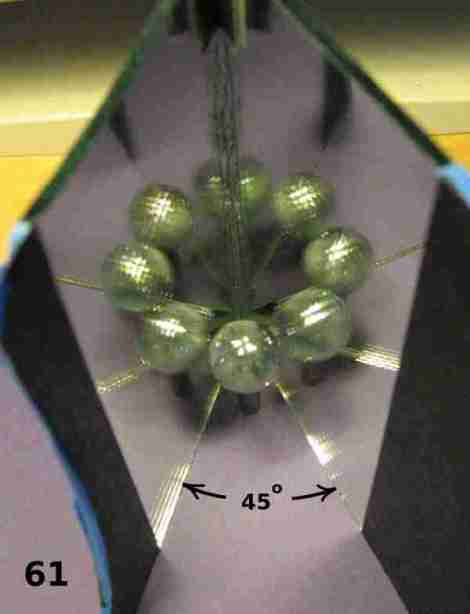
image 61

image 62

Images 57, 60, 61 and 62 show how the number of reflections of the bead increase as the angle between R1 and R2 decreases. This inverse relationship says to me that the narrower this angle the better as far as solar flux concentration.

Surely, the more images of the bead (oven cavity) the sun “sees” then the more solar flux will concentrate on the bead.

But there are several trade-offs.

As you can see, the ring of bead reflections gets gradually larger as the angle decreases. To compensate for this, the sizes or areas of R1 and R2 need to progressively increase. At some point R1 and R2 are too large and cumbersome.

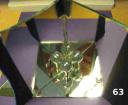
image 63

Image 63 shows how adding one more mirror, representing R3, doubles the number of bead images. Note how one of the images is lost because it is shadowed or hidden by the actual bead.

image 73

Image 73 shows how images are partially obscured when the bead is not elevated:

This is the reason that the oven chamber is elevated a bit by bowl (6).

image 72

Image 72 shows how the bead image count can be at least doubled yet again by adding the mirror that stands for R4. But, as the count and complexity of reflections increase, more and more images are obscured. There seems to be a threshold of diminishing returns.

image 66

Image 66 shows the concentrators at work. I used flash, which, I belatedly realized, is probably not good for a digital camera in a setup like this. Fortunately, perhaps most of the energy focused and dissipated on the bead instead of getting back into the camera lens.

If bead were bread, it baked.

How I Use the Kaleidoscopic Solar Oven

I use an angle of 60 degrees between R1 and R2. There may be a better angle. I have not tried others yet. I adjust the table orientation and the angle of R4 about once every 15 or 20 minutes. This needs to be done more often when the sun is high in the sky.

I frequently measure a temperature of 280 F between the top glaze bowl (1) and the lid (2), depending on the time of day. Morning hours, with the sun at a lower angle, seem to make the oven hotter than do the noon hours, probably because of the reflection obscuring effect already mentioned. Elevating the oven cavity even more when the sun is high in the sky might make the oven even hotter, but I have not needed to try that yet.

Either time of day works fine for baking my bread. The recipe for one loaf of sourdough calls for 45 minutes at 350 F in my conventional oven. I can bake 3/4 of that recipe in the Kaleidoscope solar oven in around 90 minutes. The crust browns nicely, especially on the top.

You might be tempted to let the finished bread cool just a little bit in the oven. But don’t do that. And don’t be fooled. The oven gets very hot. Be careful not to burn yourself.

While the oven is cooking, the moisture escapes as steam. As soon as the oven starts to cool, that moisture condenses on the lids and runs down to collect on the corrugated cardboard ring. The cardboard ring may dissolve if it gets wet. But, it can withstand the highest temperatures of the oven just fine. The high temperature helps keep the ring dry. As soon as I finish baking, I dump the bread on a rack to cool.

After a bit of practice, you can tell when the bread is finished baking by how it smells around the solar oven. Also, you will begin to see condensation on the inner side of glass bowl (1) when the bread is ready.

Outside of baking sourdough and cornbread, I have not yet cooked other things in this particular oven / cooker. I wonder if the condensation will be more of a problem if, for example, I make soup. I don’t know yet.

A Note on Construction Technique

Many instruct builders of these types of ovens to glue the aluminum foil to the cardboard with diluted white glue. I no longer do this.

I believe it is sufficient to bend the foil around the edges of the corrugated cardboard and fasten it in the reflective plane about every square foot using brass plated paper fasteners. Insert the fasteners through small holes prepared with a knife blade. These fasteners can be found where you get office supplies. They look like tacks with points that can be spread apart. This is much easier than working with glue. It is easy to repair.

But the main reason I do it this way is that the foil is easily removed from the cardboard when time comes to recycle them both. My red worms can eat the cardboard but the foil might not be good for them and would not be wanted in the vermicompost.

I do use white glue or carpenter’s glue to bond cardboard to cardboard where a panel needs more strength or a flap needs to be made rigid.

image 93