First Multi-Mirror Solar Oven Simulations

by Curlydock
Nov 27, 2007

nov1039a.jpg

Results published in previous posts increased confidence in my solar oven simulation program. Those tests were confined to the single-mirror configuration. By keeping things simple, results were intuitively judged. Now it gets more interesting as we encounter kaleidoscopic multi-mirror configurations with results that may challenge intuition but that are, nevertheless, we hope, still accurate.

The number of variables that define the problem make closed form expression prohibitive, at least for me. Thus, my use of simulation.

HERE IS A LIST OF THOSE VARIABLES:

The oven seems simple enough in that it is composed of two sets of hinged mirrors and a sphere called a “bounding sphere” that stands for the oven cavity. The oven cavity is the part of the oven that gets hot enough to cook food. It is constructed like a small green house, but we need not concern ourself with those details.

The bounding sphere is all we need to know about the oven cavity. The center of the sphere gives the CAVITY LOCATION in EXTENSION and ELEVATION from the “origin”, the lowest point on the vertical R1-R2 hinge. The cavity location is always in the bisecting plane of the oven’s bilateral symmetry.

The radius of that sphere gives the SIZE OF THE CAVITY. Now, to make results easier to compare across simulations, I have normalized all units of distance to the diameter of the oven cavity. So, instead of inches, feet, meters, etc, all lengths are in units of cavity diameters.

I have named the four mirrors of concern: R1, R2, R3 and R4. Hinged on a vertical axis are R1 and R2. R3 and R4 are hinged horizontally. So, we have the two angles: R1–R2 ANGLE and R3–R4 ANGLE.

We will also be concerned with where the sun is in respect to our oven, so we have: SOLAR ALTITUDE ANGLE or elevation; zero degrees on horizon and 90.0 degrees at zenith, and SOLAR AZIMUTH ANGLE. In all runs I presently contemplate, the azimuth will not change, confining the sun to the plane that bisects the symmetry of the oven.

We also have to be concerned with R1 WIDTH and R1 HEIGHT. R2 is always identical to R1 in width and height.

Since R3 and R4 are hinged horizontally, it is confusing to speak of their width and height, so I define the dimension R4 RATIO, the length of the horizontal hinge, as a portion of the opening of R1-R2.

R3 is always parallel to, or in the plane of, the horizon. R1-R2 sits on R3 like an open book with the bottom two corners on the axis of the R3-R4 hinge. Because of this configuration, the reflective part of R3 will always be a triangle with size and shape determined by the width of R1, R2 and the R1-R2 angle. The other mirrors are always square or rectangular.

R4 EXTENSION is how far R4 extends from the horizontal hinge.

Also an input variable is the QUANTITY OF REFLECTIVE PLANES. I can consider four possibilities: R3 only; R1 and R2; R1, R2 and R3; as well as all four mirrors.

I think that about covers the input variables. So far I have not concerned myself with losses based on reflective angles, surface imperfections, convection, conduction, mass, re-radiation, transmission distances, imperfect insulation, etc.

OUTPUT

What we get for output is the amount of idealized SOLAR FLUX GAIN on the oven cavity over what the cavity would have gotten directly from the sun without any concentration. This is not a temperature; it is a ratio. The minimum value will always be 1.0 unless the cavity is in shadow or blocked from direct rays, where the value could fall to zero. The maximum value depends on all the inputs.

Because of the large quantity of possible combinations of input variables, I must find a way to lock some of them down so they can be temporarily ignored. That will simplify the problem and help us make sense of where we are in our journey to the “perfect” design. I do not know if there can ever be a proof that a particular design is the best possible one. There might always be a combination of inputs hitherto unconsidered that will yield a greater flux gain than what we thought was the best. If there is such a proof, a bigger brain than my own will need to find it.

That is why I am willing to share my program listing with anyone who is interested and who agrees to keep my program or any derived from it in the public domain, not for profit.

I am also willing to do runs for others who would like to see particular results of inputs meaningful to them. Perhaps they have built an oven or two and want to see what the simulation says about comparative performance. If you are interested, just leave your request in the comments section and I may publish my response or run results in a future post.

Next, some multi-mirror runs:

For the time being I will keep R1-R2 angle at 60.0 degrees. The decision is arbitrarily based on the fact that an oven I built uses that angle. In the long run, there may be a better angle.

Also, for now I keep the width of R1 at 4.0 cavity diameters. I do that because prior runs with R3-only seemed to result in 4.0 as the optimum size for the side of R3, given the R1-R2 angle = 60.0 degrees. The length of a side of R3 is the same as the width of R1 (and R2). Lastly, to start, I make the height of R1 equal to its width.

nov1029a.jpg

Chart “nov1029a” shows the effect of cavity extension on flux gain where only R1 and R2 are in play. For these inputs, the best value seems to be 1.4, but it depends on the angle of the sun. By this chart, for sun angles higher than about 40.0 degrees we might want to make the cavity extension less than 1.4 cavity diameters.

Next, keeping cavity extension at 1.4 and everything else the same, we do four runs, one for each of four different heights of R1-R2. That results in chart “nov1030” where
red (1) = 4.0
green (2) = 6.0
blue (3) = 8.0
black (4) = 10.0
cavity diameters.

nov1030a.jpg

We see gains increasing at higher sun angles as the height of R1-R2 increases. The gain increment decreases so returns are diminishing. At this point I will make the compromise of R1-R2 height = 6.0 and keep that for the next set of runs.

I cannot resist the temptation to add more mirrors at this point. Chart “nov1032” run (1) is a repeat of “nov1030” run (2), for reference. It looks different because the vertical axis of the chart is re-calibrated to cover higher gains.

nov1032a.jpg

Note the gain still peaks at about 6.0. That gain makes sense when you consider that two mirrors at a 60.0 degree angle would allow the sun to see six images of the cavity. Run (1) is only with R1 and R2 in play.

For run (2) I merely add reflector R3 to the play, and the results show a significant increase in gain. If we consider that R3 would double 6 images to 12, the gain seen of about 9.0 makes sense, considering some of the images will be partially obscured.

Now we take a lesson from a prior post when we were testing with only R3 and learned that it is best to elevate the cavity somewhat over R3. We do just that in run (3) and see that the gain is even closer to 12.0. Supposedly, the reason is that the images are less obscured when the cavity is elevated.

In run (4) I put R4 in play and made R4 the same size and shape of R1 and R2. It is a handy size if the oven is collapsible and you stack the reflectors for storage. The solar flux gain reached 14.0. One might worry that the simulation is malfunctioning because the flux gain is below 1.0 for very low angles of the sun. More thought reveals that at these low solar angles the cavity and lower part of the oven are in the shadow of R4, so one’s confidence in the program rebounds.

Is this the best design? I doubt it. Only more testing can tell, I guess. At least, it is a benchmark for measuring more attempts.

In a future post I can make the input variables conform to the oven I have actually constructed and see what the simulation says. I will be able to compare a real oven with this benchmark and tell what changes might make it better or worse without getting my hands dirty (not meaning to disparage getting one’s hands dirty).

Last Single-Mirror Solar Oven Simulation Test

by Curlydock
Nov 24, 2007

In my previous couple of posts I showed some of the results of tests of a program I wrote to simulate what I call a “kaleidoscopic” type solar oven. In earlier posts I detail the actual oven I use to bake bread. I wanted to see how to build a better oven of this type, so I wrote the simulation for ray-tracing various reflector sizes, shapes, quantities and configurations.

This post will cover what I hope is the last of the one-reflector tests. I wish to begin tests of two-mirror simulations in the next post.

nov1026a.jpg

Graph “nov1026a” shows the results of five runs with a single equilateral triangular reflector in the plane of the horizon. That reflector I frequently refer to as “R3”. Five sweeps of the sun from zero degrees (horizon) to 90 degrees (zenith) are shown, one sweep for each size of R3. The sides are all equal and are measured in cavity diameters. The smallest R3 is 2.0 and the largest is 8.0 cavity diameters on a side. The cavity bounding sphere is represented by the ball that is aways in the corner farthest from the sun when the sun is on the horizon.

Observe that the gain never exceeds 2.0 and never falls below 1.0. This is consistent with my expectations of what happens with only one mirror and increases my confidence in the simulator.

Rule 1026a

Also observe that the increment of improvement in gain decreases as R3 gets larger. Large mirrors increase the gain when the sun is at lower angles but the reflector has to get perhaps impractically large to produce these gains. At solar angles above about 20.0 degrees, it hardly seems worth having a floor reflector larger than 4.0 cavity diameters on a side. This is more than my prejudice up until now, which was that 3.0 cavity diameters on a side was the practical limit. The actual oven I made has only 3.0. So, the next time I build one of these ovens I will probably go with 4.0. It depends on what else we learn when more reflectors are in play.

“Rule 1026a” is, then: the triangular reflector always parallel with the plane of the horizon, that is the one the cavity is above, should be sized to about 4.0 cavity diameters on a side, physical practicality permitting, and probably not less than 3.0.

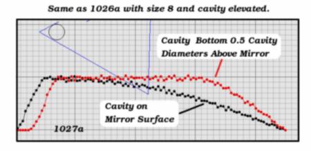
Now I combine this rule with rule 1010a from the previous post, which said the cavity should be elevated. That results in chart “1027a”:

nov1027a.jpg

For this run I kept the mirror sized to 8.0 cavity diameters on a side and elevated the bottom of the cavity from just touching R3 to where the bottom of the cavity is 0.5 cavity diameters over R3. Otherwise the run and chart calibration are the same.

Again, the gain never exceeds 2.0 and never falls below 1.0, which is good.

Also note that elevating the cavity improves gain when the sun is at higher angles. This is consistent with what we learned in the prior post and was to be expected. The simulation still seems to work. For this configuration, with the cavity elevated, the range of sun angles with the maximum gain of 2.0 is much larger.

In a prior post I expressed some doubt about whether the simulation was following the ray trace through an arbitrary number of reflections or breaking off too soon. I later discovered that was indeed a problem. But it only affected simulations of more than one mirror, none of which I had published yet. I fixed the bug and am now confident that I am ready to do multi-mirror tests. In the next post we will see some results using two reflectors. Those reflectors are the ones I have named “R1” and “R2” in prior posts. They are linked by a vertical hinge and open like a book over the plane of R3. R3 will be put aside while we consider only R1 and R2 and will return probably much later when three-mirror tests begin.

More Elementary Tests of a Solar Oven Simulation

by Curlydock

Nov 16, 2007

In the prior post I introduced a test of the simulation using only one plane of the “kaleidoscopic” type solar oven. So far, we have seen the bounding sphere of the oven cavity positioned over one triangular concentrator. That concentrator corresponds to the R3 reflector mentioned in other posts describing an actual oven that I have been using. The R3 reflector is in the plane that appears to be parallel with the earth’s surface and the cavity assembly rests on R3. In later posts we will be considering the effect of the other reflectors: R1, R2 and R4. This post is confined to more implications of the R3 reflector.

Diagrams “nov1007” and “nov1008” illustrate the oven cavity bounding sphere positioned at two different levels over the triangular reflector.

nov1007a.jpg nov1008

The red dots represent the absorption of a light ray on the surface of the bounding sphere. The blue dots represent rays reflected from the surface of the mirror that do not intercept the cavity. The shadow of the cavity can be seen on the mirror. The other dark spot on the mirror is that portion of the mirror where rays are reflected that do intercept the cavity.

This Test

The present question is how the height above the mirror affects the amount of solar flux gain the cavity will receive as the sun sweeps over an altitude angle from zero degrees on the horizon to 90 degrees at the zenith.

nov1010a.jpg

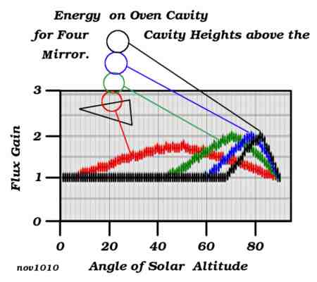
Diagram “nov1010” shows the result of four simulated solar sweeps, one for each of four different heights of the oven cavity above mirror R3.

On Units

Unless otherwise noted in these posts, the units of distance measurement will be cavity diameters. I think that is more interesting and informative than using yards or meters, etc. So, no matter what the radius of the cavity is in feet, centimeters, inches or any other unit, it is always 0.5 in cavity diameters. When the cavity rests on the mirror the center of the cavity will be 0.5 cavity diameters from the surface. The lowest point on the cavity, in that case, will be zero cavity diameters from the mirror.

The triangular mirror, R3, seen in the above illustrations and used in this particular post, is equilateral and 3.0 cavity diameters on a side. The cavity CENTER heights used to generate the data for the chart “nov1010” are 0.5 (red), 1.5 (green), 2.5 (blue) and 3.5 (black) cavity diameters. There is one color coded sun altitude sweep for each cavity placement.

The Solar Sweeps

These “altitude sweeps” are not the natural movements of the sun, so don’t be confused. The sweeps begin at the lowest point on the horizon and end at the highest point in the sky, or the zenith, at 90 degrees. The point on the horizon, zero degrees, where the sweep begins, is always in a vertical plane that bisects an angle of the triangular reflector.

The reason for this type of sweep is to see how the more complicated mirror arrangements respond to different solar angles, all of which keep the sun in the plane that bisects the symmetry of the concentrator arrangement. The purpose was to have a standardized sweep with which to compare different arrangements under any solar angle that might happen no matter what the season, location on the earth, or time of day, given that one could always adjust the oven so the sun is in that bisecting plane. Such an adjustment would not change the fact that R3 is in the plane of the horizon; it would merely rotate R3 in that plane. The tests to see how the simulated oven responds to a natural solar transit will probably be some of the last tests.

Rule 1010a

Now back to chart “nov1010”.

Note that when cavity height is lowest, 0.5, which corresponds to touching the mirror, the gain never reaches the greater levels it does when the cavity is elevated from the mirror. This is the reason for placing the inverted glass bowl underneath the oven cavity assembly, as seen in my prior posts detailing an actual solar oven. The lower bowl elevates the whole assembly a bit. I was never quite sure just how much it should be elevated but now it seems my simulations may help to determine this.

So, Rule 1010a for building kaleidoscopic solar ovens is: elevate the cavity over the mirror that is parallel to the plane of the horizon instead of letting it rest on it.

Next, we see just how much elevation is best. The above graphs suggest that the best cavity elevation will depend on the solar altitude. The angle of the sun is constantly changing; so, if we can figure out a way to easily adjust the cavity elevation about every twenty minutes, that would optimize flux gain at all times. Such a rig might be more complicated than the extra flux gain is worth, however.

Diagram “rule1010a”, seen below, might be used in the design and operation of a one-triangular reflector solar oven with an equilateral shaped mirror three cavity diameters on a side. It probably would not work for baking because the flux gain would never exceed 2.0. It might be useful for proofing bread dough or keeping a plate warm. It might also apply to ovens with more reflectors, but we have to wait to see what more tests produce to be sure.

rule1010a.jpg

This diagram allows us to determine the best cavity height above the reflecting plane for any given altitude angle of the sun. I gathered the data for the diagram from repeated runs with the simulation program. That these curves seem to make sense to me reinforces my confidence in the accuracy of the program so far (no guarantee, of course).

The runs show rather broad peaks. That suggests that a particular cavity elevation would work well for a wide range of solar angles without need to re-adjust the height. For that reason, the diagram “rule1010a” shows a region instead of a line. The acceptable region is in yellow-green between two limiting lines. The limiting lines represent the points where the solar flux gain has dropped to 0.9 times the peak value seen in the sweep. The graph seems to indicate that for solar angles below about 25 degrees there is no need to elevate the cavity at all. The flux gain might be very low, but elevating the cavity will not help.

How to Apply Rule 1010a

Here is an example of the use of diagram “rule1010a”:

Suppose the sun is at 70.0 degrees above the horizon. Find 70.0 degrees on the horizontal axis of the chart. Follow the vertical from 70 degrees up until it just reaches the green region (the first limiting line). Follow the horizontal from that point to read the cavity height. That yields about 0.70 cavity diameters.

Continue on the 70.0 degree vertical until the green region just ends (on the other limiting line). Following the horizontal from that point yields about 2.9 cavity diameters.

Therefore, the maximum gain will be when the BOTTOM (not the center) of the cavity is between 0.70 and 2.9 cavity diameters from the surface of mirror R3.

If the cavity is 12.0 inches in diameter then 0.70 cavity diameters represents 0.70 X 12.0 = 8.4 inches. Likewise, 2.9 cavity diameters X 12.0 inches per cavity diameter = 34.8 inches. At these points the gain will be about 9/10 what it would be at the peak.

To find the height corresponding to the actual peak, you can use the average. In this case, the average cavity height is (0.70 + 2.9) / 2.0 = 1.8 cavity diameters, and 1.8 X 12.0 = 21.6 inches.

In the morning and evening hours the sun is not so high and the cavity will not need so much elevation. Even if the cavity elevation is not optimum, the losses will not make the oven useless, it will probably just take a little longer to cook something. Also, when we start adding the other reflectors R1, R2 and R4, the gain will be considerably beyond 2.0, so some small maladjustments will be even less of a problem.

Initial Test of Solar Oven Simulation

by Curlydock
Nov 15, 2007

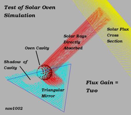
The diagram labeled “nov1002” displays a rudimentary test of my solar oven simulator. From this I hope to begin to see if the program is behaving correctly.

nov1002a.jpg

The oven cavity is seen as a ball above a triangular mirror.

A cross section of the solar flux is seen in yellow above right.

Any ray absorbed by the cavity is drawn in red. This could be either a ray directly from the sun or a ray reflected from the triangular mirror.

A ray reflected from the mirror that is not absorbed by the cavity is drawn as a short light blue vector. Any time a vector is drawn, the direction is indicated by the small ball at the end, which could be interpreted as an arrow head.

To reduce clutter in the diagram, the rays reflected and lost to space are drawn very short. They appear as a sort of light blue haze over the triangular reflector. You can see the “shadow” of the cavity on the mirror. Rays that neither hit the cavity nor the reflector are not drawn at all.

The program calculated the solar flux gain in this case to be 1.974359. This means that the cavity received almost twice as much solar radiation as it would have without any reflector at all. This is precisely what I would expect. The flux received by the cavity directly is doubled by the presence and proper placement of the mirror. The cavity would “see” two suns: one directly and the other reflected. Reciprocally, the sun would “see” two cavities, also one direct and one reflected. The analytical solar flux gain is two.

The theoretical flux gain without any reflector would be exactly one. That would be the minimum ever seen. Any properly directed reflections will increase that. The flux gain is calculated by dividing the quantity of rays absorbed with mirror concentrators in place by the quantity that would be absorbed directly from the sun when there are no mirrors. The simulation counts the rays and calculates the gain.
To see the importance of mirror orientation, we next consider what happens when the sun is at different angles, everything else remaining the same.

nov1003a.jpg

Diagram nov1003 shows how the flux gain drops to nearly unity when the sun is at a very low angle. The reason is that the triangular mirror is not of infinite extent. If it could be made large enough, we could get our gain back up to two. Thus the physical trade-off for the solar concentrator with the sun at small angles to the surface.

nov1004a.jpg

Diagram nov1004 shows the other extreme. Here, the sun is nearly at the zenith, but again the gain has dropped to nearly unity. This time the reason is that the cavity obscures the sun’s reflection. Where the cavity would “see” the sun it now only sees itself. The sun can only see the direct image of the cavity. The reflected image of the cavity is mostly hidden from the sun by the cavity itself.

These preliminary results continue to indicate that the simulation is correct.

Next, we can have the simulation sweep the solar altitude angle from zero degrees (on the horizon) to 90 degrees (at the zenith) and graph the flux gain against the solar angle. The triangular reflector is in the horizontal plane and therefore parallel with the horizon.

nov1005a.jpg

Diagram nov1005 shows the results of just such a sweep. We see the flux gain peaks at 2.0 broadly when the sun is around a 50.0 degree angle and falls to unity when the angle of the sun is either much more or much less than that.

In conclusion, the program I wrote to simulate some types of solar ovens seems to be working so far. I do still have reservations. There is more testing to do.

In future posts I hope to show the results of adding more reflecting flux concentrators. The flux gain will go up much more quickly with each added reflective plane as each added reflector exponentially increases the number of images (as in a kaleidoscope) while the increase in the number of mirrors is only linear. But limitations due to image obscuration, as we have already seen here, will subtract from the advantage of adding more reflectors, producing diminishing returns.

Some factors that affect real physics of multiple reflections I am going to ignore. I feel they would add a great deal of complexity without proportionally increasing the accuracy, at least for my purposes.

One of these factors is that every time a light beam is reflected, there is some loss. The amount of loss depends upon the angle of incidence. In my program, so far, this type of loss is not deliberately encoded. I assume no such losses.

Another factor is that no real reflector is perfect. Imperfect reflective surfaces will throw the light ray off at a non-ideal angle. Nor do I try to account for this effect.

Another factor is that I have some doubt about whether my program, as it is currently written, will ray-trace beyond about 4 or 5 reflections. I am not sure if this is true or why it happens if it does occur. I am keeping a look out for the effect but am not letting this doubt stop me from reaching for some results.

There may be other factors that have escaped my wildest dreams; who knows?

This work I put in the public domain for purposes of information and I do not claim it is perfect and suitable for just any application. If you are interested in seeing the listing, I am willing to share it. I can post it later.